1. Kit Install Overview

The basic idea of the LED kit is to replace the missing or faulty EL panels and MVS-ELA board in  Neo Geo cabinets.

The new control board can be setup for 2,4 and 6 slot games and connects to the MVS-ELA port on the side of the MVS 2,4 or 6 slot game board.

If you have the old cable you can still use this, or you can buy one with the kit.

1. Position the control board and secure it to the cabinet.

2.Align the panels to match your marquee.

3.Double check all connections and power up the game. The control board will run through a self-test and light up each panel in turn.

Once the system is running, only the panel for the game selected with light up.

That’s it. Tidy up those cables and enjoy your LED mini marquee’s.

3. The Data Connection, MVS-ELA

Next we need to get the data from the MVS to the new control board. This is the 8 pin connection on the side of the mvs next to the two 13 pin connections for the credit displays. If you have this we can use it on the new kit, just follow it up into the back of the marquee and it should be connected to the old MVS-ELA board. Remove the old board and connect the wire to the 8-pin port on the new control board. Although it only used 6 wires at the MVS end the ELA lead end also has 5v (red) and ground (black) we want to make sure the black wire goes to the pin marked GND on the new control board.

If you do not have the original ELA lead you can buy a new lead with the kit. On both ends we want to make sure the black wire is to the left when connecting to the MVS and the new control board.

Secure this in place.

4. The new control board

The new control board is Arduino based and socketed so it’s easy to replace in the future. The Arduino uses Pulse Width Modulation to control the brightness of the panels . The board has the option to show what panel should be on with LED so you can diagnose any issues you might have with data connections or panel order. The panels use screw terminals, so you can easily cut the wires to length once everything is in place. 

The control board comes with 4 feet so you can mount this to any spot in the cabinet as long as the provides wires are long enough. Once you have set the brightness there is no reason to need access to it again.


We can now connect the data cable to the control board and start to look at the panels.

5. Installing the new LED panels

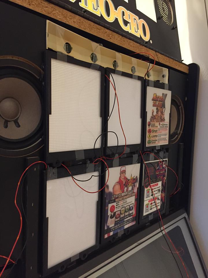
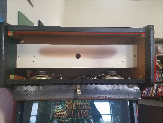
Ok so now the fun part, securing the panels to the cabinet and making sure they line up with the marquee.

The backing boards have many cut outs, so I designed the panels to have 4 screws and you just need 2 out of the 4 to secure the panels to the backing wood. Each style of cabinet has a different layout and I will be adding these as people report back to me. So far, I have confirmed a 6 slot with 3 x 2 panels and a 4 slot upright. The size of the panel was made so they can sit side-by-side and line up with the placement of the old EL panels in a 2 or 3 panel configuration.  The 4 slot upright needs the panels to be upside down compared to the 2 slot. The 6 slot with 3 x 2 needs the top and bottom rows close together and that is why the screw holes are offset. If you have the old EL panels you can just mark the backing wood and use that as a reference point to place the new panels. As I get information back I will setup printable templates to make it easier for you.


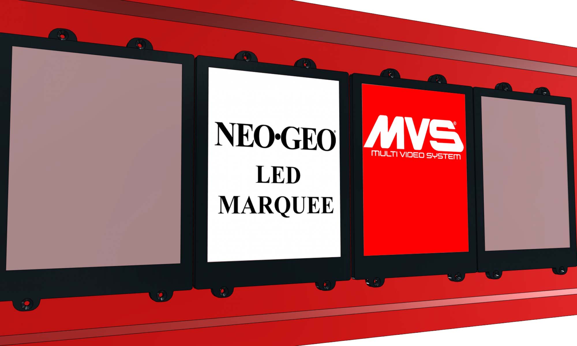
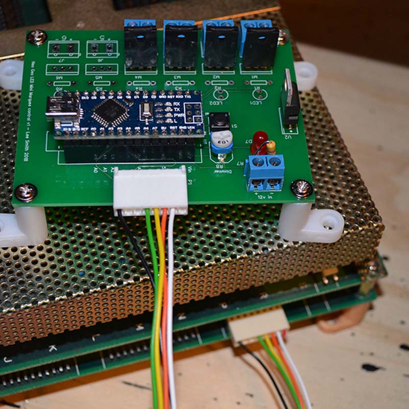
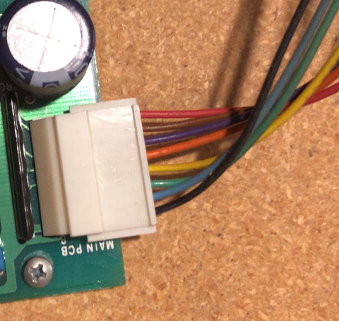
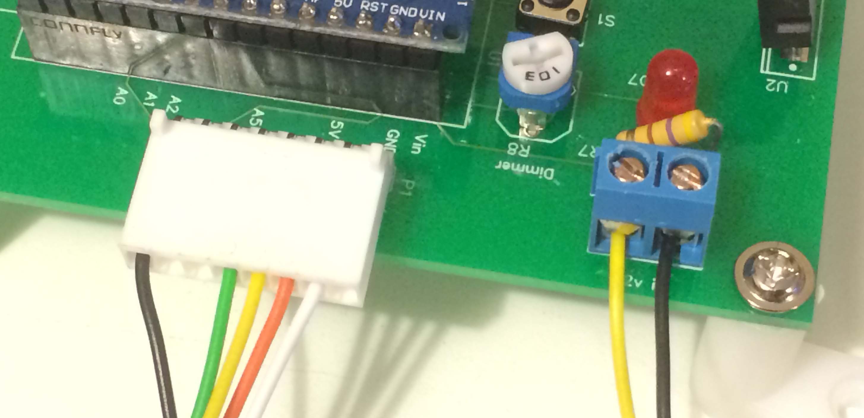
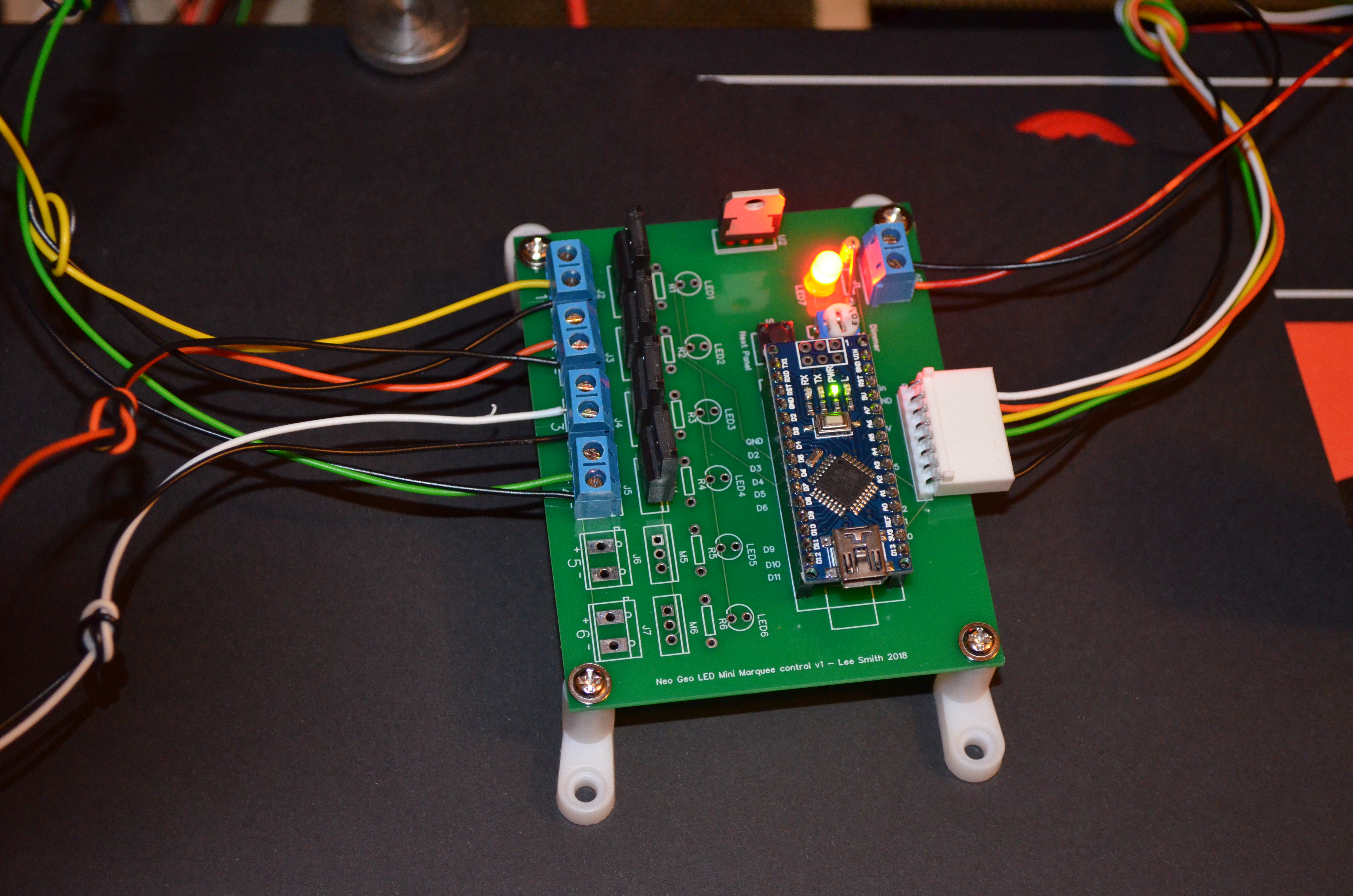
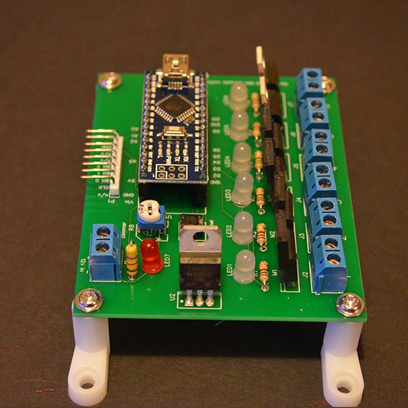
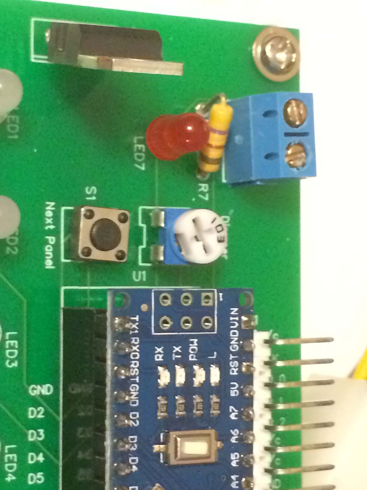
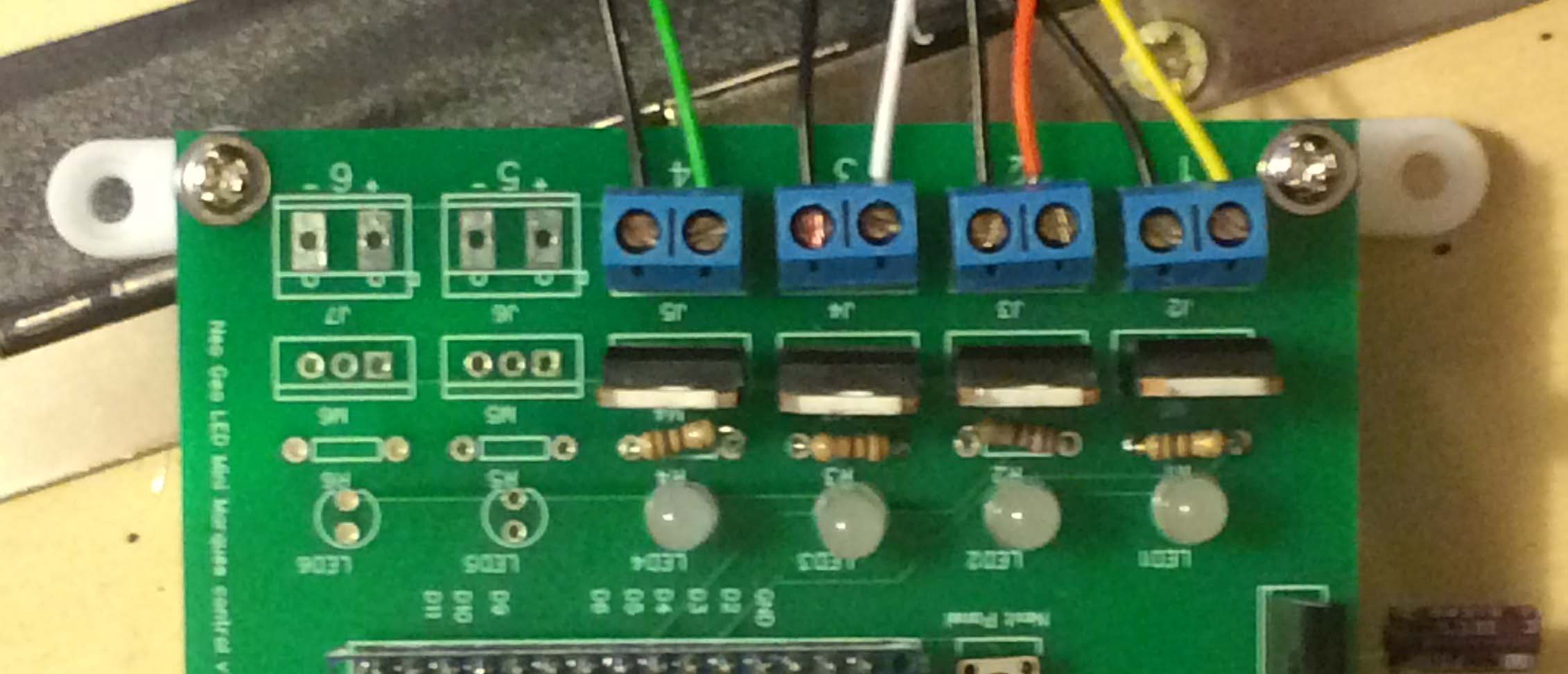
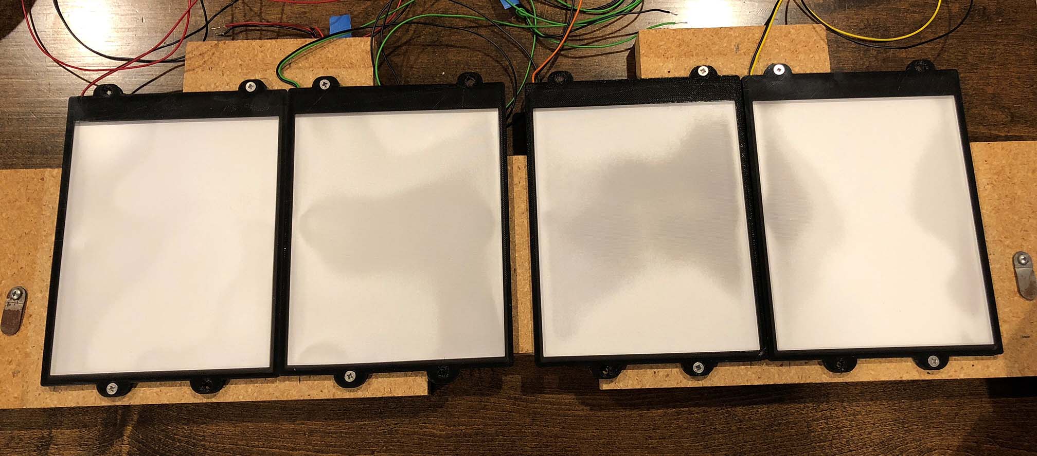
Each panel will have its own positive coloured wire and a black ground. Make sure to keep the two wires for each panel together otherwise you will have issues with wrong panel order. Once the panels are in place feed the wires to the back of the marquee section towards the location of the control board. The control board is marked with 1,2,,4 etc and + and – so just match up the colours of the panels to the number and secure with the screw terminal. You could cut the wires to size or wait until after testing.

If you have an upright-style cabinet your front marquee should have the holders for the mini marquee so you need this type of panel.

If you have a electrocoin 6 slot the space is limited so I recommend you use the style of panel with the marquee holder build in. The mini marquee just slides in the front, I have tested this with my selection of 10 mini marquees and they all slide in with minimal fuss.

With the big reg or tall boy remove the plastic mini marquee holder and slide them into the new panels.

The wide 6 slot have bigger gaps in the backing board and I supply special backing brackets to help with this.

6. Testing

If all has gone to plan we should have a data cable from the MVS to the new control board, the new led panels lined up with the marquee and the coloured wires fed back to the control board location.Before powering the game up double check all connections and make sure nothing is shorted or touching anything metallic.

As soon as you power up the cabinet the control board will run a self test and each panel should light up in turn and then panel 1 should stay lit. If you want to do a full test remove all the game cartridges or press the service switch and go to the hardware test page. This will cycle through each panel until you exit the hardware test. Look for the panels to be in the correct order as it counts up. You can use the on board white leds to check what panel should be on at any time.

The control board has a button that when pressed goes into test mode and then you can change the brightness with the small potentiometer in real time. press again to turn the panels off to check for any wiring problems and keep pressing to light up each panel. Hit reset to go back to the start.


So that should be fully working, just tidy up any wires in the cabinet and enjoy your Neo Geo with it’s new LED mini marquees.